As stated in the title, this document try to document the S-DD1 chip's algorithm and, up to certain point, the chip itself, but you have to take in mind that the main target is to describe the algorithm, not his implementation. Due to that, there are details that obviously have to be present in a real chip but that are "abstracted" in some parts of this document, like internal FIFO buffers, input and output buses, output size limitations, etc. This details are only mentioned when the author think it is convenient to do so.
The author has implemented in C++ the ideas here described, and has checked them with a lot of real examples, so he is convinced of the validity of them. Of course, it can not be claimed that the description is perfect , but, if not, it's obviously pretty close to be so. Furthermore, it has to be noted that, due to, apparently, hardware limitations, it is known that the real chip is unable to follow the algorithm in some pretty extreme cases; this will be discussed later.
Introduction
To start, let's write down in what category of compression schemes the S-DD1's algorithm fits: It is a lossless adaptive binary compression algorithm. (It is within the so-called binary entropy algorithms.) Lossless mean that the data is compressed in a way that allow the exact reconstruction of the original data; binary that it works in the bit-level (deciding the output bits one by one); adaptive that it evolve to match better the estimated probabilities of the subsequent bits. Entropy refers to the fact that that evolution goes in the direction of trying to reach the entropy limit (as defined in the information theory). There is no arithmetic methods or dictionary methods here; it is based on run-length encoding ideas; we will discuss it later.
Conceptually, we can divide most compression schemes in two parts: the raw compression properly said and the context model, that try to get advantage of the structure of the data it try to compress. In the S-DD1, the compression is based on Ricoh's technology, concretely in what they call ABS algorithm. (ABS seems to stand for Allen-Boliek-Schwartz, the researchers that signed USP#5381145, which describes this algorithm --that must be considered the corresponding patent to the S-DD1--; the patent --and others that extended it-- is pretty general, so don't expect to look at it and SEE the S-DD1, but all the ideas that the S-DD1 uses in one or another form are contained there.) This algorithm has the advantage of to allow very high speed hardware implementations, due to that it allow different parts of the chips work in a very parallelized and pipelined form. The basic idea has the ingredients of the great ideas: it is simple, elegant and efficient. It is worthwhile to take a look at the first paragraphs in the patent.
The context model in compression mechanisms use to be application specific, and this is not an exception: the different context models that the S-DD1 can adopt try to make use of the structure of SNES 8x8 tiles, as I will describe now. There are 16 such context models, and, when starting a decompression run, the S-DD1 looks at the start of the compressed data stream to know which it must to use; I will make this clear describing the structure of that stream:
Input Stream (Compressed Data)
The input stream is formed by a 4-bit header that say to the chip which context model it has to select in that decompression run, and by a sequence of variable-bit-length codewords that are fed to the internal decoders of the chip under request. It's soon to speak about the codewords, so I will now explain the context models as controlled by the header: the 4 bits can be separated in two 2 bits chunks: the first two ones describe the bitplanes' structure of the uncompressed data, and the two latter ones say which previous bits in the same bitplane are looked to form the context to a certain bit that has to be outputted. Let's be more specific:
Two first bits in the header
There are 4 cases:
00: Designed to optimize the compression of 2-bits-depth SNES tiles: that mean that the uncompressed data is supposed to have the following structure: one byte for bitplane 0, one byte for bitplane 1, one byte for bitplane 0, one byte for bitplane 1, etc...
01: Designed to optimize the compression of 8-bits-depth SNES 8x8 tiles: the uncompressed data structure is supposed to be: one byte for bitplane 0, one byte for bitplane 1, one byte for bitplane 0, etc, and when the first 16 bytes have passed (8 for bitplane 0, 8 for bitplane 1), the same occur with bitplanes 2 and 3, and after that, with 4 and 5, and by last, with bitplanes 6 and 7. When this last 16 bytes block have ended, bitplanes 0 and 1 start again and all is repeated as if the uncompressed data were formed by a sequence of 8x8 8-bits-depth tiles concatenated one after another.
10: Same as above, but with 4-bits-depth SNES 8x8 tiles, so there are only 4 bitplanes.
11: This seems to be intended to compress all that not fit in the previous ones, concretely SNES Mode7 graphics, because here there are 8 bitplanes that are formed by all the bits that occupy the same position in a byte; I mean: the sequence of lest significant bits in all the bytes form together the bitplane 0, the second lest significant bits form the bitplane 0, and so until reaching the most significant bits, that form bitplane 7.
Before continuing, a explanation is due to avoid people get confused: the algorithm is lossless, so you can use whatever of the different models to compress whatever data. The point of having different structure models is that it allow to take advantage of the knowledge we have about the structure of the data the chip is going to compress, so we can achieve, in general, better compression when the real data structure match the structure of the model.
Two latter bits in the header
When the algorithm is going to decompress one more bit, it wonder which one is the most probable symbol (MPS) to be outputted (0 or 1) and what is the probability of his appearance (that must to be greater or equal to 50%, obviously --don't take this literally; there is not a "50"; I will explain later how the probability estimation is done--). It does this by first considering in which context it is in that moment and then looking up the values for the MPS and the probability estimate stored in internal memory and associated with that context. And how such a context is determined? Looking at the parity of the bitplane in that the bit is going to be outputted is and, also, looking to 3 or 4 previous bits in the last 9 bits from the same bitplane. Looking at the parity of the bitplane makes that the contexts used for the bits that live in odd bitplanes are distinct for the context that are used by the bits that live in even bitplanes, so we have two non-overlapping sets of context. And exactly what bits in the bitplane's previous bits are looked at? This is exactly what those two bits in the header control. There are 4 possibilities of such context templates (the ordinal numbers indicate the position of the bits counting backwards):
00: 1º, 7º, 8ºand 9º
01: 1º, 8º and 9º
10: 1º, 7º and 8º
11: 1º, 2º, 8º and 9º
So, according to the case, 3 or 4 bits are looked at, and so 8 or 16 different context can be used. Taking into account that there are two such sets of context (one for odd bitplanes and the other for even bitplanes), there are 16 or 32 different context according to the case.
Added on October, 2004: As probably many people haven't noticed it (my fault, I didn't pay attention to properly explain it) I will add some words to clarify why those selections of bits are in fact pretty adequate. Let's see: as said above, the SNES' tiles are 8*8 in size, so each bitplane are composed of 8*8 bits, OK? Now, let's suppose that you have decoded the first rows of a bitplane and the next bit you should output is a bit in the middle of a row that is in the middle of the bitplane (this is only to visualize it, there is nothing special on such a bit, of course). If you were to select an adequate context using the previous bits of the bitplane, which of them do you think that would be the more reasonable selections... of course, they would be the bits that surround the bit we are going to output, that is, the bit to the left in that row, the upper bit (that is, the bit that is in the same position in the previous row), and the bit that is in the two diagonals (up-left and up-right). As we are in a 8*8 bitplane, these 4 bits correspond to the 1st, 7th, 8th and 9th bits counting backwards... do you see now why those numbers of above were selected? As you can see, they also used the 2nd bit counting backwards, that would correspond to the second bit to the left of the next bit to ouput. That bit would be, in my opinion, the fifth more reasonable bit to select, so all makes perfect sense, right?
It is time now to take a look at the internals of the S-DD1.
Functional design of the chip
The following drawing try to capture the functionality of the S-DD1 chip. This mean that, although it can be thought that it try to describe the chip itself, his intention is in fact to describe the algorithm through a description of what could be the physical implementations of his functional components; it have to be taken into account that we haven't had access to any official document about the chip, nor we have deconstructed the chip layer by layer and used a microscopy; our knowledge about the chip derive from the study of his input and output as a black box, and from the use of logic analyzers to know how it input and output data (Dark Force did some studies so). It should be noted that the real implementation can have components that are not present in the drawing, like internal buffers (we know if fact that there are at least one such buffer in the input), or have a different organization, or... Well, I repeat, it only try to describe the functionality:
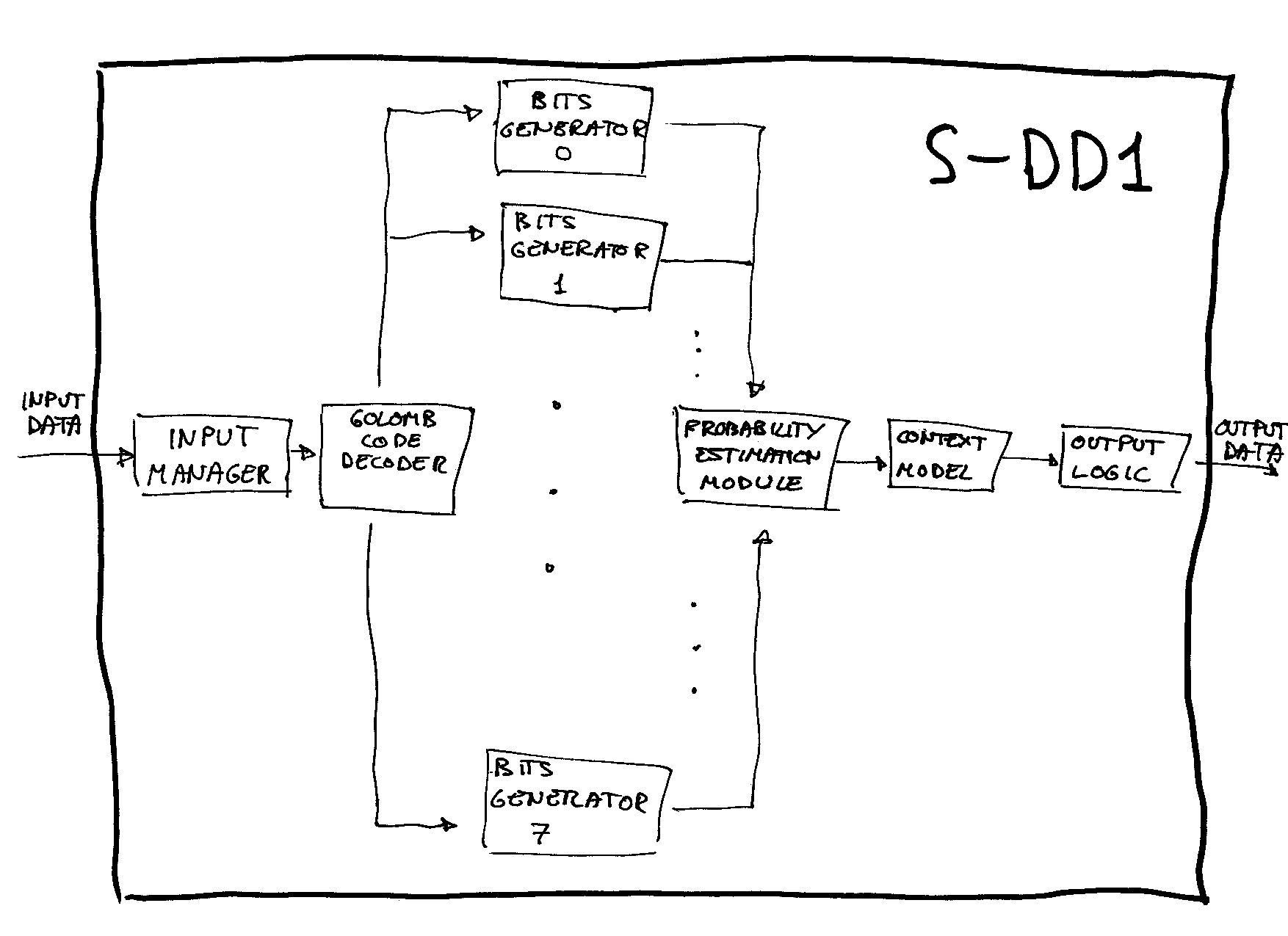
Output Logic
From an algorithmic point of view, this component control the decompression. Until all the output bits have been outputted, it ask the Context Model another bit and put it in his corresponding place (according with the bitplane structure of the output as determined by the input header --vid. Input Stream--).
Context Model
When it receive a petition from the Output Logic, it determine the corresponding context to the bit to be outputted (vid. Two Latter Bits) and ask the Probability Estimation Module a bit passing it the calculated context; when the Probability Estimation Module return the bit, it is used to update the previous bits in the bitplane and, finally, it is passed back to the Output Logic.
Probability Estimation Module
When it receive a petition from the Context Model together with a context, it uses the context to look up in memory the current MPS for that context and the current status it is in (there are 33 possible status, forming part of a evolution table). According with the code associated with the status (the codes are the so-called Golomb codes, and there are 8 possibilities), it ask to the corresponding Bit Generator a bit; this give it the bit and an indication of whether the run has ended or not; then the Probability Estimation Module develop two actions:
XOR that bit with the MPS, and return back the result to the Context Model.
If the run in the bit generator ended, it determine if the last bit was 0 or 1 and uses the evolution table to update the current status for that context and to determine if it must change the MPS for that context or not (why the last bit is determining will be understood when have been explained how are the Golomb codes).
The evolution table is the following:
| Status | Code | NextIfMPS(0) | NextIfLPS(1) |
|---|---|---|---|
| 0* | 0 | 25 | 25 |
| 1* | 0 | 2 | 1 |
| 2 | 0 | 3 | 1 |
| 3 | 0 | 4 | 2 |
| 4 | 0 | 5 | 3 |
| 5 | 1 | 6 | 4 |
| 6 | 1 | 7 | 5 |
| 7 | 1 | 8 | 6 |
| 8 | 1 | 9 | 7 |
| 9 | 2 | 10 | 8 |
| 10 | 2 | 11 | 9 |
| 11 | 2 | 12 | 10 |
| 12 | 2 | 13 | 11 |
| 13 | 3 | 14 | 12 |
| 14 | 3 | 15 | 13 |
| 15 | 3 | 16 | 14 |
| 16 | 3 | 17 | 15 |
| 17 | 4 | 18 | 16 |
| 18 | 4 | 19 | 17 |
| 19 | 5 | 20 | 18 |
| 20 | 5 | 21 | 19 |
| 21 | 6 | 22 | 20 |
| 22 | 6 | 23 | 21 |
| 23 | 7 | 24 | 22 |
| 24 | 7 | 24 | 23 |
| 25 | 0 | 26 | 1 |
| 26 | 1 | 27 | 2 |
| 27 | 2 | 28 | 4 |
| 28 | 3 | 29 | 8 |
| 29 | 4 | 30 | 12 |
| 30 | 5 | 31 | 16 |
| 31 | 6 | 32 | 18 |
| 32 | 7 | 24 | 22 |
The two states marked with an asterisk are the only states where the MPS is changed if a run end and a LPS have been received (a 1). When the decompression start, all the contexts are in state 0. If you pay attention to the table, you will notice that state 0, and all the states greater or equal than 25 can only be achieved at the beginning; after then, they never can be reached; they are what Ricoh's researchers call fast adaptation states, used only at the beginning.
Let's examine a little those Golomb Codes we have mentioned:
The fist Golomb code, G0, simply decode a bit as itself, that is, a bit 0 is decoded as 0 and a bit 1 is decoded as 1. The next one, G1, decodes a 0 as two zero bits, 00, a sequence 10 as 01 and a sequence 11 as 1; in general, the Nth-order Golomb code, GN (also denoted as R2(N) ), decodes in this manner: a zero bit correspond with a sequence of 2^N zero bits, and a 1 followed by N more bits is decoded as a run of zero bits ended by a 1, where the number of 0's (ranging from 0 to 2^N - 1) is determined by those N bits. The way in which those N bits codify the number of 0's is exemplified by the table of a G4 code:
| Coded Bits (Codeword) | Decoded Bits |
|---|---|
| 0 | 0000000000000000 |
| 10000 | 0000000000000001 |
| 11000 | 000000000000001 |
| 10100 | 00000000000001 |
| 11100 | 0000000000001 |
| 10010 | 000000000001 |
| 11010 | 00000000001 |
| 10110 | 0000000001 |
| 11110 | 000000001 |
| 10001 | 00000001 |
| 11001 | 0000001 |
| 10101 | 000001 |
| 11101 | 00001 |
| 10011 | 0001 |
| 11011 | 001 |
| 10111 | 01 |
| 11111 | 1 |
These decoded bits are the bits that will be XORed with the MPS of each context, so a 0 here mean next bit = most probable bit and a 1, next bit = least probable bit. This mean that, if the context model is capable of make good predictions, then most of the bits that the Bit Generators would have to output would be 0's. If you suppose that the decoded data is random except by the fact that the rate 0's/ 1's is fixed, then the first Golomb Code will be optimal when the numbers of both bits are approximately equal, and the higher codes will be better when one type of bit is predominant over the other. Due to this, the algorithm try to evolve to use optimal codes in each moment. It does this using the evolution table, and the idea of deciding how evolve is... looking at the previous codeword; as we have said, for a Golomb code there are two classes of codewords, a 0-codeword, and a 1N-codeword; the idea is that if a 0-codeword has been read, that mean that the context model is doing a pretty good job predicting the next bits and, then, to use a higher code would be beneficial; in the other hand, if a 1N-codeword has been read, then probably we should consider that maybe a lower code would be better. Because of the codewords are characterized only looking at the last bit they output, this last bit is all what the Probability Estimation Module need when it is going to change the state in the table. This is a very clever way of adapting the probabilities that doesn't involve arithmetic and can be easily and efficiently implemented in hardware.
Let's continue with the description of the components:
3.4 Bits Generator
There are 8 of these, all of them coupled to the Golomb Code Decoder; this latter is the responsible of decoding the codewords in the way we have just explained, and the Bit Generator store the run count of 0's. Really, the Bits Generator only need to store the number of 0's to be outputted and an indicator of whether or not a 1 is present at the end. So his working is so:
When it receive a petition from the Probability Estimation Module, it does the following:
If the count of 0's is null and the LPS indicator is off, then it ask to the Golomb Code Decoder another run.
Next, it looks at the count of 0's; if it is not null, it return a 0 bit and decrement the count. If the count is null, then the LPS indicator must be on, and so it return a 1 and put the indicator to off.
Furthermore, it return to the Probability Estimation Module an indicator of whether the last bit has been outputted (to indicate to the Probability Estimation Module that it has to update his state).
Golomb Code Decoder
The Golomb Code Decoder receive petitions from the Bits Generators. When one of these Bits Generators ask another run count, it ask to the Input Manager another codeword or order N (where N would be the corresponding order to the Bit Generator that made the petition) and decode it in the way we have indicated above, passing back to the Bits Generator the count of 0's and an indicator of whether or not a 1 is present at the end.
Input Manager
When it receive a petition of a codeword of order N from the Golomb Code Decoder, it examines the next bits in the input stream and cut a corresponding 0-codeword or 1N-codeword, returning it to the Golomb Code Decoder.
It should be noted that this design try to allow that the context model and the decoding part of the chip can work in a pipelined form; in fact, the Ricoh's patent allow greater parallelism, due to that the codewords are packed in fix size chunks and, so, the input manager don't need to expect a request to know how to cut the input stream. Moreover, the decoder could ask more input data in advance, without expecting a request from the Bits Generators, and have a buffer to store the next codewords. Why the S-DD1 doesn't implement all these ideas? Whether is the correct answer or not, the most obvious answer would be that simply it doesn't need it; his design, although not taking full advantage of the parallelism it could to have, allow it to output data fast enough to satisfy the requirements of the SNES's DMA logic.
Having done the effort to explain all this stuff, I think I should to seize the opportunity to talk about the inverse function, that is, the compression algorithm.
A Possible Design of a Compressor
We haven't had access to any compression chip or software, but, once you have understood the S-DD1's algorithm, it is easy to inverse the function and construct a compression algorithm. Here you have another drawing:
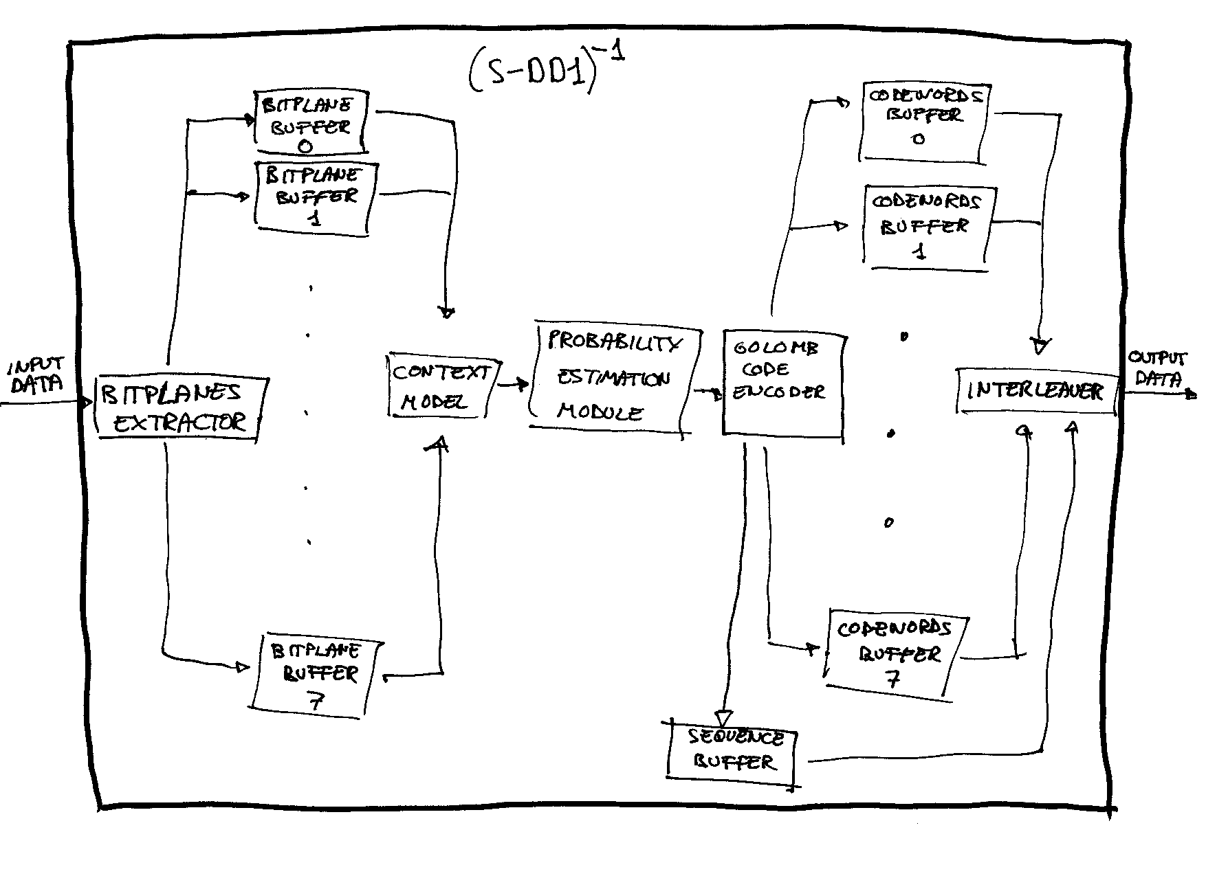
Again, I have implemented the described ideas in C++ and checked them. You must note that other functional descriptions (variants of this) for a compression system could be imagined; this is irrelevant for me, the present description is clear enough and it work well. Due to all the explanations when describing the decompression, now the description of the components doesn't need to be so extensive:
Bitplanes Extractor
It split the input stream (the original data to be compressed) into different bitplanes (according to the bitplanes structure that the context model use) and store them in buffers.
Context Model
When it receive a petition from the Probability Estimation Module, it extract a bit from the bitplane that correspond in that moment, calculate the context (in the same way as in the decompressor) and send both to the Probability Estimation Module.
Probability Estimation Module
Until all the data has been compressed, it ask the Context Model a bit and a context, obtain the MPS and current state of the corresponding state, XOR the bit with the MPS and send the result to the Golomb Code Encoder (indicating to it the code associated with the current state of that context). If this latter component return back a signal saying that that bit has been the last bit needed to output a codeword, the current state is updated following the evolution table looking at the last bit generated (just like in the decompression).
Golomb Code Encoder
The Golomb Code Encoder receives the bits to be encoded from the Probability Estimation Module together with the codes to which those bits are associated. It outputs the codewords to the appropiate buffer (i mean, there are 8 codewords' buffers associated to the Golomb Code Encoder, one for each code --- from G0 to G7 ---); when the last bit needed to output a codeword is received, it send a signal back to the Probability Estimation Module. When the first bit to determine a codeword is inputted, it add his code order at the end of another buffer, the sequence buffer.
This last buffer is intended to store the sequence of codewords to be outputted in the final output. That is, the 8 buffers that store the codewords will have to be interleaved, and that sequence buffer say how the interleaving has to be done. Why this interleaving is not done on-the-fly? A example will clarify this: suppose that in a certain point of the stream buffer, a 7-order codeword has to be outputted (this mean that the first bit that will make the codeword has been received by the encoder); the point is that maybe (depending of each case) you will have to expect until a lot more bits (until 127) has been used in contexts that be in the 7th-order code before knowing which is the exact codeword to be outputted, and, until then, a lot of other codewords corresponding to bits whose context are in distinct codes had probably had to be outputted. Do you notice the problem? A certain buffer storage is needed. Of course, this could be done in different ways that would allow semi-on-the-fly interleaving, but I think this method is the cleanest.
Interleaver
As just explained, it use the sequence buffer to interleave the codewords stored in the 8 buffers associated to the encoder.
Perfect Emulation?
The author has done validations against thousands of examples, comparing the results of his programs with the real answers of the chip (my thanks go to The Dumper for providing me with data) so he is sure that only pretty minor differences could be present in the algorithm (and, personally, he really thinks there are no such differences), but, I repeat, in the algorithm; we know for sure that there are extreme examples where this algorithm don't match the behavior of the real chip. Although it could be (and it has been) discussed, the writer has a personal security on which the problem is, and that it is due to hardware limitations (maybe call this a bug is not appropriate).
To start, let's see how we observed the problem by first time: Doing some validations against real data extracted from SFA2, we saw a mismatch; after using the programs to do some logging of information, I observed that the problem arose when the chip read a part of the input which, annoying!, more than 600 1's without any 0 between then. Days after, I noticed that, really, this was not a mismatch with real data, because, looking at the real data within the decompression pack from Dejap, I notice that at most 832 bytes were asked by the S-DD1 in that decompression, and we had our problem in around byte #5000 of an output of 8 KB. So this pointed out to that that mismatch didn't be a mismatch in real data; the problem seemed to be that our output were too long and, so, we have considered as compressed data a number of bytes that in fact was not intended to be so, I mean, those strange 1's. By the way, the observed phenomenon in the data outputted by the chip were that, when reaching that point, it looked like to stop his working and not update the byte presented to the DMA logic any more; so, the same byte was repeated in the output stream forever.
We could reproduce easily this behavior: creating files with random data in around the 256 first bytes (well, not completely random; the number of 0's were forced to be greater that the number of 1's) and then inserting a lot of 1 bits, we could see that phenomenon in around 130/256 attempts. After a couple of days of looking at the logs (and of desperation), finally I noticed what was the only common pattern that all the mismatches had. Think on this a little: suppose that, in a certain moment, the context are in high codes, but, unexpectedly, a lot of 1's are present in the input stream (the compressed data). What this mean? that the input codewords are of the type 11...11, and, if you take a look at the Golomb Codes, this mean that those codewords only output a unique bit. So a lots of input bits are needed to output only one; the I/O rate is risen a lot (the maximum would be 8, corresponding to 7-order codewords). What is the problem with this? That, in every DMA cycle, the S-DD1 must output 8 bits and it only can receive 16 bits, so the maximum I/O rate it can support during long periods of time is 2. Of course, if this high rate only occur during little time, there is no problem because it is clear that the S-DD1 has a input FIFO buffer, but if that stressing conditions are maintained for a while, finally the chip hangs.
In fact, I have at least two interesting examples where the hang almost occur; they occur just in the end of those 1's, and it looked like the hang phenomenon started but, suddenly, the sequence of 1's end, the I/O rate is lowered and the hang is avoided in the last moment . When I thought this I didn't have still the compression program, but, when I did it, I compressed both real outputs (from the chip) and compared them with input we have fed to the chip. That is what I observed: when reaching the zone in that the problem was happening, I only noticed one difference: a byte in the original data was duplicated in this data compressed with the algorithm, and all the subsequent bytes were equal (but, obviously, displaced a byte). For me, the interpretation of this is clear: when, finally, the chip can not support such I/O rates any more because they internal FIFO input buffer are empty, when more data need to be read, and so the buffer underflow the last byte in the buffer is incorrectly fed as if it were normal input; in those two cases, just in that moment the I/O rate decrease and the hang is avoided, but, if not, if the problem continue, the chip finally hangs at all. If must be noted that the in those two examples, the bytes where this phenomenon occur have distinct parity; I mean: in one example it occur in a even byte and in the other in a odd byte.
Why not all the tests showed this phenomenon? There are two causes: or they don't needed to reach the part of the compressed stream where the 1's were to output all what we have asked, or they did, but they reached that zone in smaller codes and then... no problem. I insist: the difficulties arise when the I/O rate is high, and for this it is necessary that the context be in high codes; if low codes are being used, then the I/O rate would be less than 2, and no problem will arise. I want you notice some facts:
- The fact that this phenomenon arise makes that some data can not be compressed (because, yes, the data with those 1's would correspond to a certain original data; although weird original data, it should be said).
- This phenomenon depends heavily of the velocity of the buses, so if you would connect the chip to a slower input bus/control logic, you would see this phenomenon arising before. It is not a stable phenomenon. It depend heavily of external conditions (external to the chip, I refer).
- There is no way to use this phenomenon to your own benefit when compressing data in a clean way, because you only could use I in some very specific points (where high states were used), and to reach it, you would need to previously rise the I/O rate, so you could not control the form of the previous bytes (because only some codewords would be allowed to achieve a high I/O rate).
- It must be noted that, if you compress data with a certain header, the sequence of necessary input bits to generate this phenomenon is a complete statistical abnormality; but, if you select the best of the 16 compressions (with the 16 headers), the abnormality is still pretty bigger. I can not believe this phenomenon can arise when compressing real life data.
Random Comments
Looking at the data in which the patent's application was filed, we can say that Ricoh had the necessary know-how to design such a chip as soon as in the late 1992.
As said before, the S-DD1 don't take full advantage of all the capabilities the design allow; we could say that the S-DD1 is a low-end implementation of the ABS algorithm.
Now it can be easily understood why almost all the real data in Star Ocean has its first byte in the range 0x80-0xbf; these are the values for which the first two bits in the header are 11, and this mean that a context model optimized for 4-bit-depth graphics is used, ...and these graphics are the most used in Star Ocean.
The highest compression rate the algorithm can reach is 128:1.
The worst asymptotical rate that can be reached with a fixed header is 2:3 (it would correspond to all the contexts switching forever between states 4 and 5 in the table.
Here is the included C++ compressor/decompressor and example usage:
_By Andreas Naive (August 15th, 2003 - October 2004)